

Installing rooftop mechanical equipment can optimize space, reduce noise pollution and streamline maintenance. The equipment must resist wind and seismic loads and be able to transfer the loads to the host structure via an anchor system.
Traditionally, curbs—elevated platforms integral to roof structures—have been used when installing rooftop mechanical equipment. Curbs should be appropriately flashed, securely attached and sealed as part of a roof system. Extensive planning and strict coordination between the design team and tradespeople often lead to a rigid approach with limited flexibility for accommodating changes.
Recently, a new, more flexible installation method has emerged that seeks to further optimize the deployment of rooftop mechanical equipment by eliminating field fabrication.
Engineered roof anchor systems
Because of the low invasiveness and modularity of securement, engineered roof anchor systems can streamline rooftop mechanical equipment deployment following roof membrane installation. Some engineered anchor solutions align with manufacturer warranties despite the penetrative methods by which the anchors are mechanically fastened to the structural deck. This provides a path for tension loading.
In the aftermath of several hurricane seasons, Federal Emergency Management Agency Mitigation Assessment Teams have consistently highlighted the vulnerability of rooftop equipment to wind damage. Wind-induced failure of rooftop equipment, such as exhaust fans, HVAC units, relief air hoods, ductwork and boiler stacks, can result in these components being forcefully dislodged from their positions, including supporting curbs, access panels and sheet-metal enclosures.
Dislodged equipment turned into wind-borne debris poses risks to buildings, property and individuals. The most common issues are inadequate anchorage, equipment strength and corrosion. This suggests securing rooftop equipment to resist wind loads is essential to protecting the integrity of the building envelope and avoiding exposing the building’s interior to higher wind loads and possible water intrusion. This billowing (ballooning) effect is a well-recognized phenomenon; the wind-uplift pressure, or the difference in pressure across the membrane, can balloon the roof membrane as much as several feet vertically between seam lines (see Figure 1).
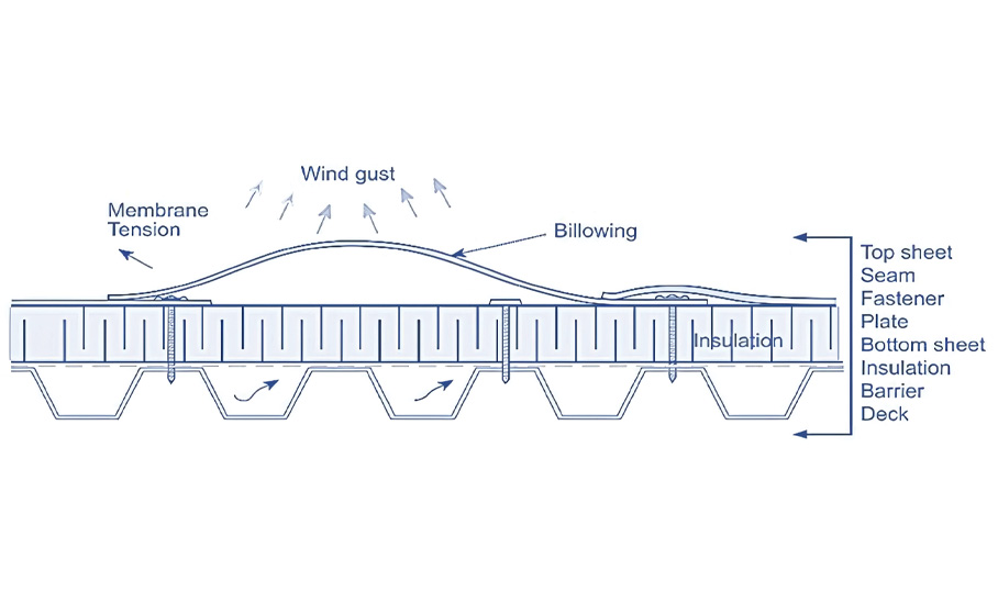
Wind kinetic energy, a function of wind speed and air density, preloads a rubber roof membrane with elastic potential energy. Proper mechanical attachment of a roof membrane around curbs eliminates the possibility of loose membrane balloons contacting and transferring loads to rooftop mechanical equipment; roofing plates and fasteners dissipate the elastic energy.
In contrast, arbitrary positioning and elevating rooftop mechanical equipment on prefabricated support structures such as metal frame kits and trays on mechanically attached roof systems can negatively affect anchor system installation. In these situations, the membrane can balloon and contact the rooftop mechanical equipment system, placing an additional load currently undetected by load standards.
Load standards, such as ASCE 7, “Minimum Design Loads and Associated Criteria for Buildings and Other Structures,” and others, aim to regulate the safe deployment of rooftop mechanical equipment by providing structural designers with analytical methods to properly size an anchor system as a function of wind speed.
Rooftop mechanical equipment load standards resolve total wind impact into horizontal (overturning) and vertical (uplift) forces. However, load standards are insensitive to roof system type and possibly underestimate the total load transfer of wind kinetic energy onto rooftop mechanical equipment, specifically on mechanically attached roof systems.
The billowing of a single-ply roof membrane under wind-uplift pressure can cause a significant load transfer from a mechanically attached roof system to rooftop mechanical equipment. Ongoing experiments at the Bronco Construction Research Center at Western Michigan University, Kalamazoo, Mich., show rooftop mechanical equipment anchor points can be stressed beyond current load standards when deployed on mechanically attached roof systems.
Dynamic roofing facility
Wind-uplift testing can quantify the load transfer between single-ply roof membrane balloons on mechanically attached roof systems to rooftop mechanical equipment, specifically measuring the impact of clearance between rooftop mechanical equipment and roof membrane and evaluating the significance of the relative position of an anchor to a seam. These findings can be compared with load standards to provide a better appreciation and awareness of this issue.
The dynamic roofing facility at Bronco Construction Research Center can accept up to 24- by 12-foot, 18-inch-thick low-slope roof specimens under uniform static and cyclic loading up to 300 pounds per square foot uplift pressures (see photo). The facility comprises a lift-operated top chamber with viewports and a bottom reactionary table frame. The wind-uplift chamber operates via a closed-loop control system employing a fan blower (100 horsepower), servo-controlled flap valve (simulating wind gusts), controller and pressure sensors. A primary pressure sensor is used for control feedback. Two secondary pressure sensors deployed in the opposite corners of the chamber verify pressure uniformity across the system.
The dynamic roofing facility applies four target pressure levels (25, 37.5, 50 and 75 psf) to the rooftop mechanical equipment using 30 gusts per target pressure following CSA A123.21-20, “Standard Test Method for the Dynamic Wind Uplift Resistance of Membrane-roofing Systems.” Each gust is 8 seconds (T1) and consists of a 4-second target pressure component (T2) enveloped by transient periods followed by a 2.4-second zero pressure component (T3). The dynamic response of the rooftop mechanical equipment unit to the chamber suction was captured as a time history of four load sensors.
A full-scale mechanically attached roof system mockup was constructed with an HVAC unit attached using four load sensors (load cells) embedded in a series with their anchor points reacting against the frame of the dynamic roofing facility.
Clearance below raised rooftop mechanical equipment is crucial in reducing load transfer
Results
During the wind-uplift application inside the dynamic roofing facility, the load transfer to rooftop mechanical equipment from ballooning of the membrane in a mechanically attached roof system resulted in significant damage to the HVAC unit.
Impact of clearance
Load transfer significantly varies depending on the clearance between mechanically attached roof systems and rooftop mechanical equipment across all pressure levels. Jurisdictional standards and industry practices may establish a minimum clearance of 4 inches, historically tied to using 4- by 4-inch dimensional lumber sleepers for supporting rooftop mechanical equipment. Although this dimension has been adopted in some cases for modern engineered supports and anchor systems, current guidelines often recommend greater clearances (e.g. 6 to 18 inches) to accommodate drainage airflow and maintenance access, depending on local building codes, equipment manufacturer guidelines and specific site requirements.
-4.jpg)
At lower pressure levels, an increase in clearance to 8 inches markedly reduces the load transfer from 473 pounds to 225 pounds, achieving a reduction of more than 50% (see Figure 2). However, at higher pressure levels, the advantage of increasing the clearance decreases the reduction in load transfer to less than 30%. This highlights the importance of considering clearance when designing a mechanically attached roof system, particularly its effectiveness in reducing load transfer and varying pressure levels.
Impact of position
During one experiment, the HVAC unit was secured to the dynamic roofing facility frame at four points arranged in a 16- by 16-inch square. The four anchor points and associated load cell apparatus were not evenly spaced with the mechanically attached roof system seam lines and the edges of the dynamic roofing facility frame table as depicted in the schematic shown in Figure 3.
The four anchor points of the rooftop mechanical equipment sustained variable load transfer from the mechanically attached roof system across all pressure levels (see Figure 3). Consistently, load cell 1 captured the highest load across all pressure levels, trailed by load cells 2, 3 and 4. At 25 psf and 75 psf pressure levels, load cell 1 captured 166 pounds and 518 pounds of uplift load, respectively. In comparison, load cell 4 at these pressure levels sustained only 70 pounds and 257 pounds of uplift, respectively.
-5.jpg)
In summary, the uplift load recorded by load cell 1 was 137% higher at 25 psf and 101% higher at 75 psf compared with those measured by load cell 4, indicating a substantial difference in tensile load distribution between the two anchors. The anchor load positively correlates with the membrane area, creating a ballooning load. Increasing the distance of an anchor point from a seam line increases the uplift force on an anchor.
To illustrate, the anchor on load cell 1 was impacted by a mechanically attached roof system balloon measuring 3,725 square inches, and the anchor on load cell 4 collided with a balloon measuring only 2,950 square inches. Larger balloons possess greater elastic potential energy and transfer greater loads onto an anchor system than smaller balloons.
Wind load calculations
The uplift force (Fv) exerted on a rooftop HVAC unit is determined following the minimum design loads standard in ASCE 7, which considers several factors: velocity pressure (qh), wind directionality (Kd), gust effect (GCr) and top surface area of rooftop mechanical equipment (Ar). In ASCE 7-22, equation 29.4-3, this relationship is expressed as: Fv = qh × Kd × GCr × Ar
For instance, with given values of qh = 25 psf, Kd = 0.85, GCr = 1.5 and Ar = 4 ft2, the calculated uplift force is 127.5 pounds. This analysis explicitly represents the uplift force caused by aerodynamic wind flow. According to ASCE 7 load analysis, the uplift forces for this scenario range from 128 to 383 pounds, corresponding to a pressure level spectrum of 25 to 75 psf.
However, empirical data from a more stringent 4-inch clearance scenario reveals uplift forces ranging from 473 pounds to 1,560 pounds across the same pressure spectrum. These empirical results indicate uplift forces can be between 270% and 308% higher than those predicted by standard load analysis methods.
The interaction between the ballooning of a mechanically attached roof system and its rooftop mechanical equipment predominantly influences the load transfer mechanism observed in the dynamic roofing facility. Specifically, hydrostatic conditions within the dynamic roofing facility chamber negate any uplift effect on rooftop mechanical equipment as demonstrated in the study’s setup.
In the tested scenario, the wind-uplift table generated no uplift force on the rooftop mechanical equipment; all anchor reactions resulted solely from the membrane ballooning against the equipment frame. This observation underscores the critical role of the roof membrane’s dynamic behavior when influencing load transfer mechanisms under wind-uplift conditions.
Takeaways
We note the following conclusions and recommendations from the experiments:
- Engineered roof anchor systems can optimize rooftop mechanical equipment deployment by eliminating field fabrication, standardizing components and reducing weight.
- Wind-induced failure of rooftop equipment is common. Securing rooftop mechanical equipment to resist wind loads is essential to protecting the integrity of the building envelope and avoiding exposing the building’s interior to higher wind loads and possible water intrusion.
- The load transfer from mechanically attached roof systems to rooftop mechanical equipment as a result of membrane ballooning can be significant. Clearance below raised rooftop mechanical equipment is crucial in reducing load transfer. Increasing the clearance from 4 to 8 inches can reduce the load transfer by more than 50% at lower pressure levels.
- The relative position of an anchor to a seam also affects load transfer. Load cells closer to seam lines capture lower loads than load cells farther away. The size of a wind-borne roof membrane balloon in contact with a rooftop mechanical equipment system determines the uplift force on an anchor.
- Wind load calculations based on load standards in ASCE 7 may underestimate the uplift forces on rooftop mechanical equipment. Empirical data from a 4-inch clearance scenario shows uplift forces that can be 270% to 308% higher than those predicted by ASCE 7. Continuous improvement of rooftop mechanical equipment anchor system designs that consider ballooning effects is recommended.

Bilal Alhawamdeh, Ph.D.
Senior research associate
Bronco Construction Research Center
Western Michigan University
Brian Montgomery, P.G.
Director
Bronco Construction Research Center
Western Michigan University
Ondre Pekarovic, ME
Research engineer
Bronco Construction Research Center
Western Michigan University

-1.jpg)
-1.jpg)